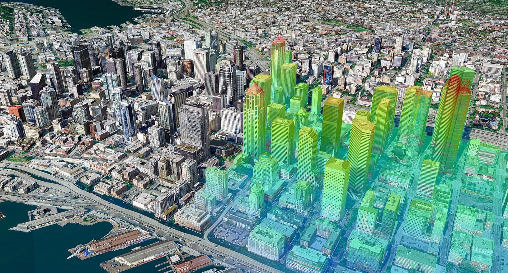
In Part 3, we solved the problem of geometric optimization by using XPath to precisely extract the LOD level that meets project requirements (e.g., <bldg:lod2Solid>). However, a classic error scenario often occurs immediately afterward: despite having a structurally sound model that has passed all XML Schema validation steps, when engineers proceed to import this data into Unity, Unreal Engine, or WebGIS platforms, the model either doesn’t display, floats tens of meters above the ground, or its entire mesh structure is broken.
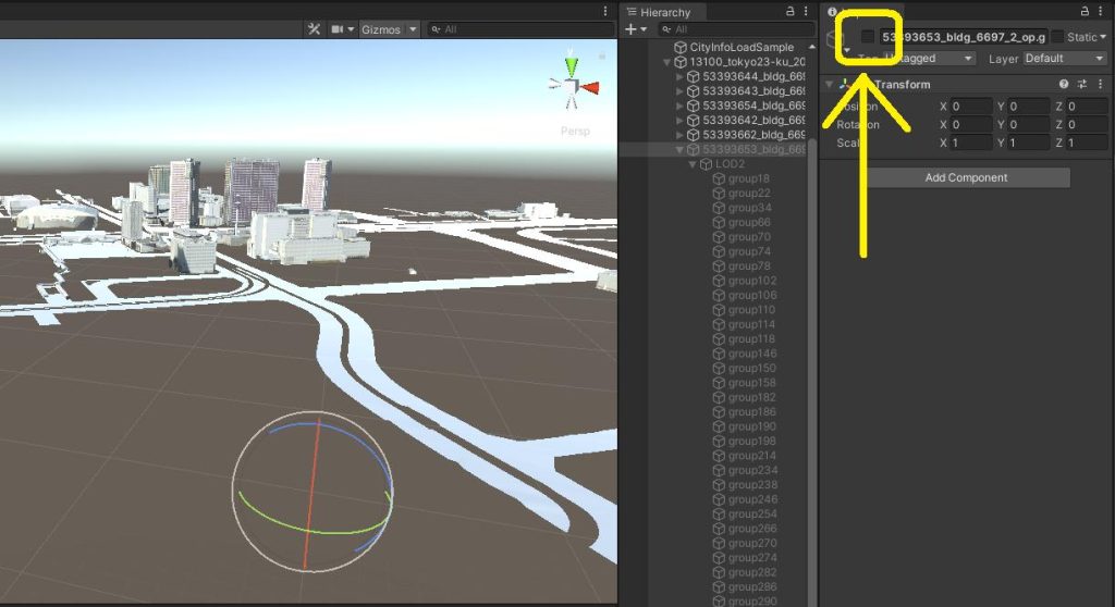
The core reason for this situation is not a corrupted data file. The problem stems from your Data Pipeline lacking an essential spatial processing procedure: establishing a Coordinate Reference System (CRS) and aligning the Elevation.
This Part 4 article will conclude the Urban Digital Twin series by definitively addressing the final stage of the pipeline: Accurately positioning 3D models onto real-world coordinates and analyzing 3 serious technical errors that need to be fixed when integrating 3D GIS data into Graphic Engines.
1. The Coordinate Problem: Do Not Use Geographic Coordinates for Measurement
When receiving 3D GIS data, the most common mistake engineers make is importing raw datasets directly into Graphic Engines without configuring a Coordinate Reference System (CRS).
Current Situation from OGC Standards and Real-world Data According to the OGC CityGML standard, the coordinate reference system for the entire model is explicitly declared in the srsName attribute within the <gml:Envelope> tag. This data will be inherited by the entire internal geometric structure. Taking an example from Japan’s open data repository PLATEAU, CityGML models are typically provided under EPSG:6697 (belonging to the JGD2011 system). Similarly, in Vietnam, data collected from aerial devices (Drone/LiDAR) is often exported under the international standard WGS84 (EPSG:4326).
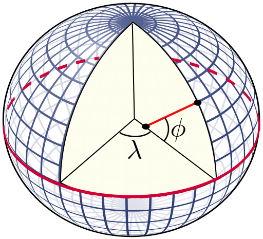
The commonality of these systems is that they belong to the Geographic Coordinate System, representing space through longitude and latitude. In cartography, the Geographic Coordinate System is only suitable for global positioning. If this coordinate system is used in a 3D environment, engineers will be completely unable to accurately calculate Area, Volume, or the actual dimensions of a structure.
Actionable Insight: Establish Coordinate Transformation To solve the problem of accurate measurement and display in Graphic Engines, engineers must add a Coordinate Transformation step to the Data Pipeline. The goal is to convert data from a Geographic Coordinate System to a Projected Coordinate System, using meters as the unit.


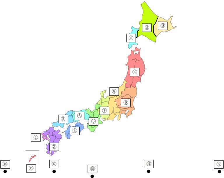
- Reference from Japan: Japanese engineers address this issue by converting from EPSG:6697 to 19 separate projected coordinate zones to minimize projection errors. For example, the entire Tokyo area is designated to be converted to Zone 9 (EPSG:6677).
- Application in Vietnam: Similarly, you cannot use raw WGS84 for urban simulation projects. The Data Pipeline needs to be configured to transform the data to the national coordinate system VN-2000 with an appropriate projection zone.

Automation Tooling For city-scale model projects, CRS conversion should absolutely not be done manually. System engineers should use programming tools for batch-processing:
- Utilize the open-source
pyprojlibrary in Python. By initializing aTransformerobject, the system can automatically read XML files and accurately calculate coordinate transformations. - Implement the integration of core libraries like GDAL (via the
ogr2ogrcommand) or specialized ETL platforms such as FME Form to smoothly process tens of thousands of CityGML files simultaneously before exporting to graphics formats.
3. Three Technical Errors When Importing 3D GIS into Graphic Engines
Converting CityGML to graphic formats like FBX, OBJ, or glTF is not enough. Engineers need to immediately review the following 3 configurations to ensure stable model operation and avoid display errors:
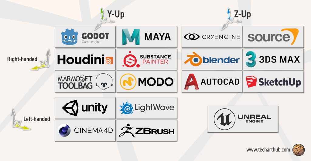
- Error 1: Axis Swapping. GIS data always defines the Z-axis as the elevation axis (Z-up). However, environments like Unity default to a Y-up coordinate system. If the axis swap configuration step is omitted during import, the entire city model will be rotated 90 degrees horizontally.

- Error 2: Float Precision. Projected coordinates calculated in meters often contain very large values (e.g., X=5438350.0). Graphic Engines by default use
32-bit floatdata types (accurate to a maximum of 7 digits), causing coordinate vertices to be rounded and merged incorrectly. The consequence is a broken mesh structure or jittering when the camera moves.- Actionable Insight: Configure spatial calculation logic to use
64-bit double, only usingfloatfor the final graphics rendering step.
- Actionable Insight: Configure spatial calculation logic to use
- Error 3: Origin Offset. Projected coordinate systems like VN-2000 or JGD2011 have an origin point (0,0) located hundreds of kilometers away from urban areas. When imported, the model will be pushed too far beyond the virtual space’s calculation limits and automatically hidden by the system (Camera Culling).
- Actionable Insight: It is mandatory to implement the Origin Shift algorithm directly within the pipeline process. Engineers need to extract a central coordinate (Center POI) of the project, then subtract this POI value from all original coordinates of the CityGML file to shift the model to the correct (0,0,0) Local coordinates before exporting the graphics file.
4. Standardizing Elevation and Terrain Matching
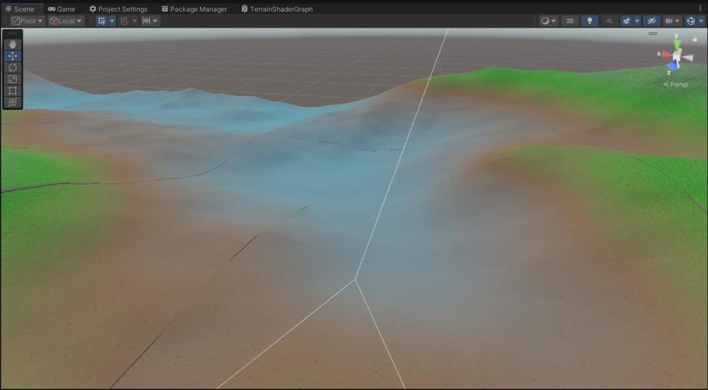
Handling elevation discrepancies is a mandatory task to prevent 3D models from floating or sinking below the ground when rendered on Graphic Engines.
- Ellipsoidal vs. Orthometric Height: GPS/GNSS data usually returns Ellipsoidal Height. However, urban standards like PLATEAU require Orthometric Height (referenced to mean sea level).
- Actionable Insight: In the data pipeline, it is mandatory to set up a Geoid offset algorithm to synchronize the actual elevation for the entire model. (In Vietnam, engineers need to use the Hon Dau hydrographic station as a reference point).
- Extrusion Peculiarities of LOD1: LOD1 models are constructed from the median height value of the Point Cloud. For structures with wide bases, using the median height will cause the model to appear significantly lower than reality. This tolerance needs special attention when setting up simulation tasks.
- Terrain Matching: The real-world surface always has a slope. The most common error is hardcoding Z=0 for all structures.
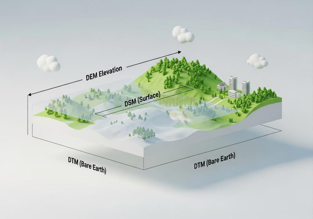
- Actionable Insight: Always load Digital Elevation Model (DEM) data into the pipeline. In CityGML, this terrain layer is declared via the
dem:ReliefFeaturenode under TIN or Raster structure. The DEM layer will serve as the base surface for the model’s base coordinates to perfectly snap to the terrain’s undulations.
- Actionable Insight: Always load Digital Elevation Model (DEM) data into the pipeline. In CityGML, this terrain layer is declared via the
4. Summary: Establishing a Standard Data Pipeline
Looking back at the entire process from Part 1 to Part 4, we can systematize 3D GIS processing into an automated data pipeline comprising 5 core steps:
- Parse & Validate: Use scripts to parse CityGML files, check XML Schema validity, and remove unnecessary namespaces (Parts 1, 2).
- LOD Extraction: Apply XPath to precisely query the LOD level (e.g.,
<bldg:lod2Solid>) to meet project Use-case requirements, removing redundant geometric details (Part 3). - Coordinate Transformation & Origin Shift: Integrate
pyprojor GDAL to transform the Coordinate Reference System (CRS) to the VN-2000 projected system, simultaneously executing the origin shift algorithm to the Local Origin to prevent rendering errors (Part 4). - Metadata Decoupling: Use
UUIDas the Primary Key, decouple all non-spatial attributes for storage in a relational database (such as PostgreSQL / PostGIS) to facilitate real-time queries (Part 2). - Format Export: Export geometric structures to graphics formats optimized for front-end streaming (such as 3D Tiles, glTF, FBX).
Conclusion
Building an Urban Digital Twin is not merely a 3D graphics display problem; it is about the ability to manage Spatial Data, Semantic LOD structures, and master Coordinate Systems. By strictly adhering to the technical principles throughout this series, your engineering team can fully design and deploy city-scale systems with high stability, hardware optimization, and practical operational value.