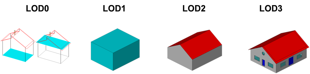
In Part 1, we established a core principle: CityGML is the Semantic Single Source of Truth (SSOT) for the entire project, while formats like 3D Tiles, OBJ, or FBX are merely output formats for display purposes. If one attempts to pursue a 3D model that is visually rich but semantically poor, the project will fail as soon as it enters the analysis and simulation phase.

However, the gap between the concept of storing data using the original standard and actually processing the files is a very challenging problem. When receiving CityGML source data, weighing tens of GBs, from a vendor, it is strictly forbidden to throw it directly into a data pipeline (like FME) or 3D engines (Cesium, Unreal). Blindly parsing a massive XML file without understanding its internal structure will directly lead to Out of Memory (OOM) errors or system crashes.
To answer the question at the end of Part 1: ‘How do you know if your dataset contains the correct objects, attributes, and structure for the problem?’, you must systematically inspect and validate the data using the following process before incorporating it into the production pipeline.
1. OGC Open Standard & The True Nature of CityGML
OGC (Open Geospatial Consortium) is an international organization dedicated to establishing open standards for geospatial data. Within this ecosystem, CityGML is a core standard (GML3 application schema) used for storing and exchanging 3D city models.
Do not confuse CityGML with pure graphic formats like FBX or OBJ. CityGML is a text-based XML database format. CityGML’s key strength lies in its ability to maintain the integrity and strong linkage between geometry, topology, and semantics through its LOD (Level of Detail) structure.
2. “Anatomy” of CityGML’s Internal Structure
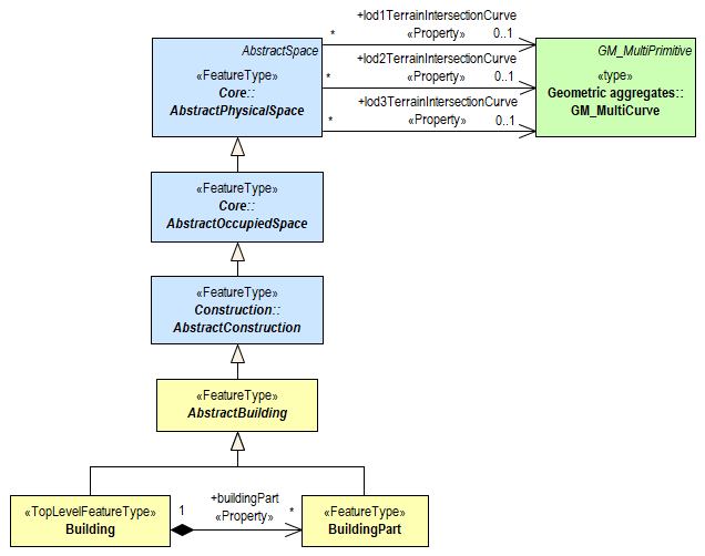
The CityGML structure is highly modularized through XML Namespaces. Instead of cramming everything together, it divides data into independent spaces such as core, bldg (building), tran (transportation), or veg (vegetation).
Below is the backbone schema of a CityGML file:
XML
<?xml version="1.0" encoding="UTF-8"?><core:CityModel xmlns:core="http://www.opengis.net/citygml/2.0" xmlns:bldg="http://www.opengis.net/citygml/building/2.0" xmlns:gml="http://www.opengis.net/gml"> <!-- 1. Bounding Box & CRS: Tọa độ ranh giới và Hệ quy chiếu --> <gml:boundedBy> <gml:Envelope srsName="urn:ogc:def:crs,crs:EPSG::25832"> <gml:lowerCorner>458868.0 5438343.0 112.0</gml:lowerCorner> <gml:upperCorner>458892.0 5438362.0 117.0</gml:upperCorner> </gml:Envelope> </gml:boundedBy> <!-- 2. Feature Node: Chứa object thực tế --> <core:cityObjectMember> <bldg:Building gml:id="UUID_7b1a5a6f-ddad"> <!-- Metadata (Semantic) --> <gml:name>Building A</gml:name> <bldg:yearOfConstruction>1985</bldg:yearOfConstruction> <!-- Geometry & LOD --> <bldg:lod2Solid> <gml:Solid> <gml:exterior>...</gml:exterior> </gml:Solid> </bldg:lod2Solid> </bldg:Building> </core:cityObjectMember></core:CityModel>When reading the code above, engineers only need to focus on parsing 3 main nodes:
<gml:Envelope>: Defines the bounding space (Bounding Box) and Coordinate Reference System (CRS).<core:cityObjectMember>: Identifies the object type.<bldg:lodXSolid>: Defines the geometric structure corresponding to the LOD level.
3. Actionable Checklist: 5 Steps to Systematically Validate Data
How to know if the CityGML file delivered by the vendor meets the correct objects, attributes, and structure for the problem? Follow these 5 validation steps sequentially before importing data into the system.
Step 1: Validate XML Schema (XSD)
- Action: Do not rely on visual inspection. Run a Python script (using the
lxmllibrary withiterparsemechanism to avoid consuming all RAM) or dedicated tools to compare the entire file against the standard OGC XSD set (e.g.,core.xsd,building.xsd). - Reason: Vendors often define non-standard custom tags or omit namespace declarations. Skipping this step will cause the target map engine’s parser to encounter Fatal Errors and immediately crash the system.
Step 2: Inspect the Coordinate Reference System (CRS/EPSG)
- Action: Read the
srsNamevalue in the<gml:Envelope>node. GML specifies that this original CRS will be inherited for the entire internal geometry structure. - Practical Bottleneck: Data collected from aerial devices (Drone/LiDAR) often returns raw data in the international WGS84 coordinate system (
EPSG:4326). Inserting it directly into a local map engine will cause the model to be off by tens of meters. You must determine the current CRS to configure a Transform tool (via FME or GDAL/ogr2ogr) to convert the coordinates to the VN-2000 planar coordinate system (e.g.,EPSG:3405for Hanoi) before rendering.
Step 3: Profile Object Type & LOD Geometry using CLI/XPath
- Action: Absolutely do not trust file naming conventions like
District1_LOD2.gmlorBridge_Data.gml. Open a Terminal and usexmlstarletorgrepto quickly inspect the density of actual object tags inside:Bash# Command to count and classify objects based on XML Namespace xmlstarlet el hanoi_citygml.gml | sort | uniq -c - Case study:
- If the file is named
Bridge_Databut the CLI command returns only<bldg:Building>tags without<brid:Bridge>, reject the file immediately after 3 seconds. - If the problem is solar radiation calculation (solar panel), the system needs to extract roof pitch. If the XPath query returns only
<bldg:lod1Solid>tags (simple block – extruded polygon) instead of<bldg:lod2Solid>or<bldg:RoofSurface>, this dataset is completely useless.
- If the file is named
Step 4: Validate Referential Integrity
- Action: Use the Schematron engine to run the
referentialIntegrity.schrule set provided by OGC to automatically check internal cross-reference relationships. - Reason: To optimize file size, CityGML often uses the
xlink:hrefattribute pointing to agml:idto reuse geometry structures or apply textures. When vendors segment files by spatial grids, it is very easy to break links, leaving href tags pointing to a ‘dead’ ID. The consequence when displayed on WebGIS is a model with torn structures (broken polygons) or completely shattered textures.
Step 5: Map UUID and Extract Attributes According to Use Case
- Action: Scan and extract attributes that determine the analytical capability for the problem (e.g., a flood simulation requires checking the
<bldg:storeysBelowGround>tag to get basement information). Concurrently, check the uniqueness of thegml:idkey. - Practical Bottleneck: Currently, 3D city models produced by various entities often suffer from being ‘graphic-rich but metadata-blind,’ completely lacking basic cadastral information. Do not attempt to stuff text attributes into the XML file as it will unnecessarily inflate the file size.
- Optimal Solution: Use
gml:iditself as the Primary Key (PK). Keep the CityGML XML file lightweight (storing only geometry and core attributes) to smooth the rendering pipeline. All cadastral information and detailed planning records should be stored separately in a relational database (PostgreSQL/PostGIS) and joined with the 3D model in real-time via this UUID.
Conclusion: Mastering Structure is Mastering the Pipeline
Once you have mastered the ability to inspect CityGML structures, you no longer rely on opening software and praying it runs. You control the quality of input data, knowing whether it meets the requirements of real-world problems.
Read Part 3: We will delve into the concept of LOD (Level of Detail) in CityGML – one of the most misunderstood elements in urban Digital Twin projects. The question is not how to make the model ‘more detailed,’ but rather: What level of LOD is sufficient for the problem, and why is indiscriminately increasing LOD a trap that collapses the entire operating system?